CVR & FDR
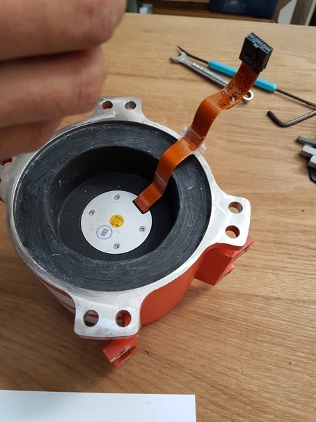
Disassembly & Chip Access
AAI 101

Course Overveiw

In some catastrophic aircraft accidents, the CVR and FDR are so badly destroyed that it becomes impossible to use standard data downloaders for flight data retrieval. In such cases, where even the CSMU memory interface cable has been destroyed, the only remaining alternative is chip removal and reinsertion. It will be necessary to disassemble the CVR or FDR, enter the CSMU, and access the all important memory chip for direct reading or for reinsertion into backup CSMU’s. In this course, you will acquire hands-on experience with Cockpit Voice Recorder (CVR) and Flight Data Recorder (FDR) ‘disassembly/reassembly’ and Crash Survivable Memory Unit (CSMU) EEPROM chip removal

Practice fire fighting, before the fire happens!

CSMU Chip Access Skills

Disassembly techniques vary between CVR and FDR models. First time disassembly can be a nightmare. Join our course and learn how to access the memory chips of today’s most popular black boxes

Prepardeness

The investigator must always be prepared for the unexpected. Mastering this skill set in advance, will expedite your aircraft accident investigation when chip recovery is mandatory.

Independence

No need to depend on the OEM for CSMU chip retrieval. We’ll employ CMM’s where necessary to guide you through the entire process.

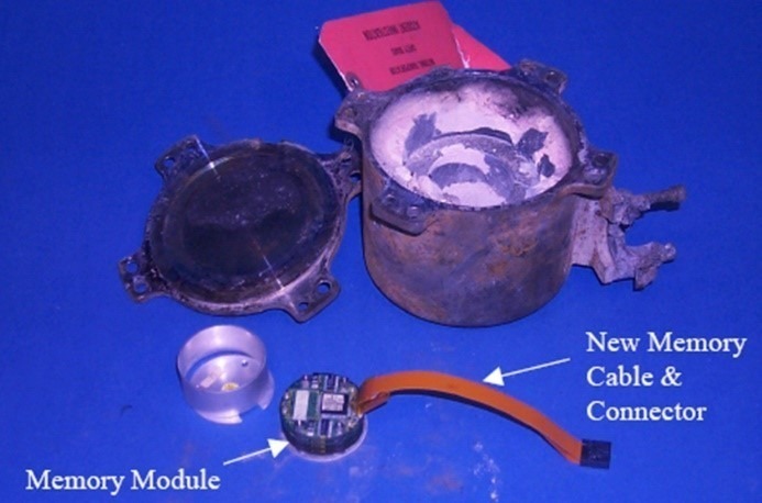
Speak with an investigator who had to swap memory chips, and you’ll immediately understand why this is a must course for all aircraft accident investigators. When a black box gets smoked in a serious aircraft accident and you are left with a damaged CSMU, you’ll need to plug that CSMU into a functional CVR or FDR. Great! That works when the CSMU is in tact, but what if the ribbon cable has been destroyed?

Bring your tools, or use ours, because this is a hands-on pratical course.

“I am pleased and excited to share that the FDR/CVR Disassembly Training I attended in 2017 at Flight Data X LLC has equipped me with the essential technical knowledge and skills required to disassemble and recover data from various flight recorders, including magnetic tape and solid-state models. This training offered valuable insights into crash-survivable memory units (CSMU), focusing on their structure and assembly, memory module identification, appropriate tooling and procedures, and effective data retrieval techniques for damaged recorders. The hands-on experience I gained during the training has increased my confidence in retrieving critical data for Annex 13 Aircraft Accident Investigations and significantly enhanced my technical skills, which I have applied to improve our flight recorder laboratory’s capabilities.”

Emerson Buidal
Manager-Engineering Investigations / Laboratory  
PNG Accident Investigation Commission

Learn more about how AAI 101 can benefit your organization

Learn more about how Flight Data Simulation can benefit your organization.

Learn more about how DAE for Aerospace can benefit your organization

How do I modify my FDR to record more than 25 hours?

You can modify the program pins at the rear of the SSFDR to uptick your recording hours. For example, if you have a Honeywell PN 980-4700-XXX installed, you can alter the ‘ground/open’ discrete wiring at pin 17 & 18 of the SSFDR mating connector to increase your recording capacity.

How can determine the amount of hours recorded by my FDR?

The amount of recorded hours is dependent on a combination of your FDAU wps output and FDR maximum allowable recording speed. If there is a one to one relationship between the two units, i.e. – 64 wps FDAU with a 64 wps FDR, you will record the last 25 hours of flight data. This also applies to the case when the FDAU and FDR are both 128wps, 256wps, or even higher. If there is a mismatch between the FDAU and FDR speed, a small and simple calculation can be made to determine actual flight hour recording capacity. See the figure below for the various possibilities:

How can I determine the speed of my Flight Data Recording system in words per second (wps)?

There are basically 4 ways to determine your speed, with the 4th being a bit more involved. First, the speed should be listed or documented in chapter 31 of your aircraft Maintenance Manual and/or Wiring Diagram Manual. However there are times when for some reason, the required information cannot be found. If this is the case, as a second method, you may reference the CMM or technical specification for your Flight Data Acquisition Unit (FDAU). If you are still unable to find this information, you may contact the aircraft manufacturer for the wps or review your previous FDR download analysis reports. Please keep in mind, the OEM will only know the as-delivered configuration of your aircraft. If there were modifications to your aircraft post-delivery – manufacturer unaware of the changes – youll need to contact us for an analysis of your raw data. Using our software we can determine the wps of your system.

With regard to Flight Data Recorder Systems, what exactly does wps imply? I have noticed this abbreviation in our FDR documentation and in communications with the manufacturer several times:

WPS = words per second. A word (12-bits in length) contains binary data which represents a specific parameter value. Please see figure 1 below. Your FDR records in frames (4 second intervals) and each frame contains 4 sub frames (one sub frame = 1 second). With each second that goes by a specific quantity of words are recorded into memory. If you operate a 64 wps FDR system, you will record 64 12-bit words in one second. The higher the word capacity the more information you can record.

What is a Dataframe Layout (DFL)?

A DFL, also known by the name Logical Frame Layout (LFL), Dataframe Interface Control & Requirements Document, and many other names depending on the manufacturer, is a document which specifies the FDR, QAR, or DAR Parameter Word (location), Recording Speed, Sampling Rate, Bits, and Conversion formulae for your recording system.  

Contact our Team

Contact our Team