Why bother with all the FDM software setup, event severity thresholds, event monitoring, and reporting? Leave the data crunching to us!
With our state of the art software, not only do we present the resultant data to you in several different formats (i.e. – 3D animation, 2D graphs, tabular format, dashboards, etc..), but we analyze the data and reveal areas of high risk, to help you avoid events, incidents and even accidents from occuring.
Sign up for our FDM solution, and we will:
Acquire & process your data
Extract intelligence and trends
Issue weekly, monthly, and annual reports
Provide Gatekeeper services
Track pilot performance
Correlate FDM & CVR data via our Audio Data Monitoring (ADM ®)
Support Event & Incident Investigation
Provide AOG analysis
Issue auto alert notifications when alert levels are exceeded
Integrate with your Flight Safety & Flight Ops department
Assist with flight data parameter calibration & troubleshooting
FDM for Flight Ops...of course!, but for Flight Training as well! Awesome!
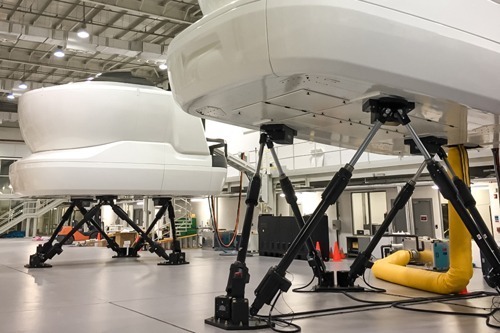
Could it be that your % of Go-Arounds for Unstable Approaches are not increasing simply because Go-Arounds are not enforced or being practiced enough during pilot training in the sim?…or…how about the excessive hits for flap extensions below 1000 ft AFE, caused by pilots who are sim trained to reference RA instead of AFE as the limit. This major break through will allow you to benefit from the first combined FDM/FOQA and Flight Training Monitoring program in the industry. You guessed it! Just like you monitor your everyday Flight Operations using FDM/FOQA software, you can now monitor your Flight Training program in your Full Flight Simulators (FFS) and Flight Training Devices (FTD), and use the data to drive improvements in your flight training curriculum. Whether it’s manufactured by Teledyne, Honeywell, or SAGEM, we’ll integrate the acquisition unit into your sim and assist with recertification at the same time. Options are available for wireless, cellular, and manual sim flight data collection.
Learn more about how Flight Data Simulation can benefit your organization.
Learn more about how DAE for Aerospace can benefit your organization
How do I modify my FDR to record more than 25 hours?
You can modify the program pins at the rear of the SSFDR to uptick your recording hours. For example, if you have a Honeywell PN 980-4700-XXX installed, you can alter the ‘ground/open’ discrete wiring at pin 17 & 18 of the SSFDR mating connector to increase your recording capacity.
How can determine the amount of hours recorded by my FDR?
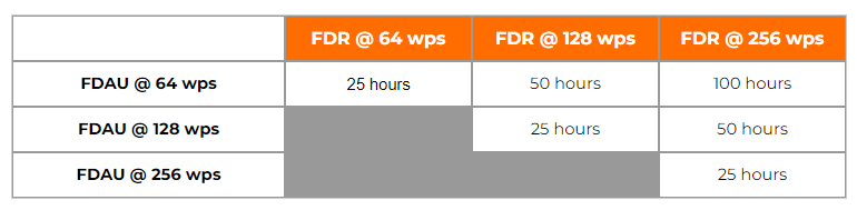
The amount of recorded hours is dependent on a combination of your FDAU wps output and FDR maximum allowable recording speed. If there is a one to one relationship between the two units, i.e. – 64 wps FDAU with a 64 wps FDR, you will record the last 25 hours of flight data. This also applies to the case when the FDAU and FDR are both 128wps, 256wps, or even higher. If there is a mismatch between the FDAU and FDR speed, a small and simple calculation can be made to determine actual flight hour recording capacity. See the figure below for the various possibilities:
How can I determine the speed of my Flight Data Recording system in words per second (wps)?
There are basically 4 ways to determine your speed, with the 4th being a bit more involved. First, the speed should be listed or documented in chapter 31 of your aircraft Maintenance Manual and/or Wiring Diagram Manual. However there are times when for some reason, the required information cannot be found. If this is the case, as a second method, you may reference the CMM or technical specification for your Flight Data Acquisition Unit (FDAU). If you are still unable to find this information, you may contact the aircraft manufacturer for the wps or review your previous FDR download analysis reports. Please keep in mind, the OEM will only know the as-delivered configuration of your aircraft. If there were modifications to your aircraft post-delivery – manufacturer unaware of the changes – youll need to contact us for an analysis of your raw data. Using our software we can determine the wps of your system.
With regard to Flight Data Recorder Systems, what exactly does wps imply? I have noticed this abbreviation in our FDR documentation and in communications with the manufacturer several times:
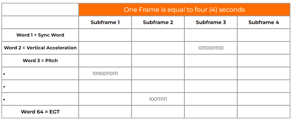
WPS = words per second. A word (12-bits in length) contains binary data which represents a specific parameter value. Please see figure 1 below. Your FDR records in frames (4 second intervals) and each frame contains 4 sub frames (one sub frame = 1 second). With each second that goes by a specific quantity of words are recorded into memory. If you operate a 64 wps FDR system, you will record 64 12-bit words in one second. The higher the word capacity the more information you can record.
A DFL, also known by the name Logical Frame Layout (LFL), Dataframe Interface Control & Requirements Document, and many other names depending on the manufacturer, is a document which specifies the FDR, QAR, or DAR Parameter Word (location), Recording Speed, Sampling Rate, Bits, and Conversion formulae for your recording system.