
Flight Data Simulation

Flight Data Simulation can solve some of your most challenging anomalies
At our advanced flight data analytics lab, we employ flight data simulation to solve all sorts of industry parameter, acquisition, transmission, and recording issues. We’ve applied flight data simulation to everything from flight data certification and test up to and including support for military level data analytics and diagnostics.
Customer A used our flight data simulator for black box data erasure to avoid data theft during transit of the unit to the repair station.
Customer B flew our in-class aircraft simulator which generates flight data parameter outputs in order to grasp the essentials of FDM analysis.
Customer C is interested in applying our flight data simulator in a troubleshooting environment where the signal line between the DFDAU and SSFDR is suspect.
How will you apply flight data simulation to solve some of your challenges?
FAQ’s
View our Q&A list to understand how flight data simulation is applied!
We need to ship our SSFDR to the factory for repair, but it contains latitude and longitude, flight numbers, and other identifying information. We would hate for this critical information to fall into the wrong hands in the event the SSFDR does not reach it’s final destination. Can you provide us with a method or device for erasing the SSFDR data before we ship it?
Absolutely. Our Labworx T717 mini-DFDAU transmits ARINC 717 data and has been employed for erausre of SSFDR data in the past. You can rent or purchase the unit based on your operational needs.
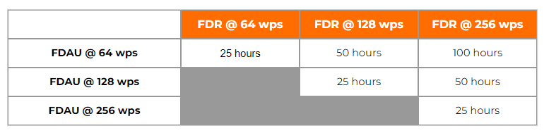
I can’t seem to find the recording speed capacity of my SSFDR in any documentation. Our system underwent several modifications in the past and unfortunately the paper trail does not provide any clues. How can I apply flight data simulation to solve this mystery?
By simulating the flight data input to your SSFDR, we can determine your recording capacity. For example if we transmit 64wps from our Labworx T717 transmitter into your SSFDR and discover 50 hours of data, this would equate to an SSFDR recording capacity of 128wps....so forth and so on.
We need to upgrade our DFDAU dataframe from 256 to 512wps. While we do believe recording parameters at a higher sampling rate will improve the fidelity of our FDM program, we lack hard core proof in the form of analytics, which is making it difficult to justify the cost and benefits to upper management. This may be an edge case but we are wondering if flight data simulation can be used to generate the required substantiation?
For this one, we will allow you to fly the flight simulator at our laboratory and study the various parameter sampling rate outputs, in all phases of flight, and in various extreme conditions and aircraft attitudes, both in graphical and tabular format. From this exercise, you will record and plot the dynamic recording range and data points under varying rates of change which will provide you with the exact proof you are searching for.
We need to accomplish a full functional test of all SSFDR recorded parameters. Our AMM does not provide a test procedure for this. Can you assist us with simulating or developing the missing test procedures?
Sure, this is one of our favorites. It can be quite difficult to test certain parameters without the aircraft being airborne and in a state which accomodates advanced parameter tests and validation. We’ll use ARINC 717, 429, and other databus transmission protocols to simulate and stimulate your aircraft recording system while on the ground, thereby eliminating the need for factory testing.