Intermediate
Cockpit Voice Data Analysis
CVA 201

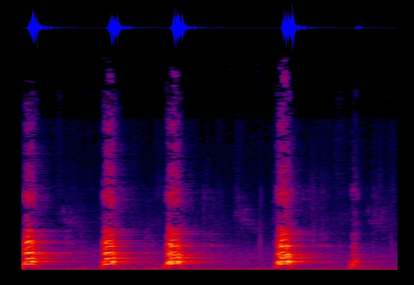
Your first Quiz? What is the difference between a Spectrum and Spectrogram analyzer?

Take your CVR audio analysis skills to the next level. After completion of CVA 101, you are now ready to measure, dissect, and troubleshoot a wide range of industry recognized CVR audio defect types. You will work directly with live examples of electrical and mechanical saturation, poor amplification, audio data loss, GSM interference, CAM recording pollution, and a plethora of other anomalies. At a minimum you will walk away with the ability to both quantify and qualify CVR audio from an amplification, signal integrity and noise perspective.

Prerequisite:

Add the following skills to your CVR analysis portfolio

Audio Defect Recognition

You can’t fix what you can’t detect. You’ll discover how to search for and recognize the various types of audio defects

Audio Defect Measurement

After detection, you’ll measure, quantify, and qualify the various types of anomalies to determine the severity of the defect

Audio Defect Removal

You’ll explore ways to remove the defects so that you can recover the CVR audio for the investigation

In addition to noise and interference detection, measurement, and removal, this course will guide you in the detection and separation of crew voices as well.

Sample Case: “During the CVR audio investigation, we didn’t detect the V1 callout by the co-pilot due to the sound of the engine fire bell.”

Solution: Use the voice separation module mastered in CVA 201 to suppress the engine fire bell so you can determine if the co-pilot actually called out V1.

“I didn’t know so many filters existed. We learned all about the Kalman filter, low pass, band pass, high pass and other filters, which I will definitely apply in my CVR audio work going forward. ”

Al Musaafir
Flight Data Asia

Learn more about how CVA 201 can benefit your organization

Learn more about how Flight Data Simulation can benefit your organization.

Learn more about how DAE for Aerospace can benefit your organization

How do I modify my FDR to record more than 25 hours?

You can modify the program pins at the rear of the SSFDR to uptick your recording hours. For example, if you have a Honeywell PN 980-4700-XXX installed, you can alter the ‘ground/open’ discrete wiring at pin 17 & 18 of the SSFDR mating connector to increase your recording capacity.

How can determine the amount of hours recorded by my FDR?

The amount of recorded hours is dependent on a combination of your FDAU wps output and FDR maximum allowable recording speed. If there is a one to one relationship between the two units, i.e. – 64 wps FDAU with a 64 wps FDR, you will record the last 25 hours of flight data. This also applies to the case when the FDAU and FDR are both 128wps, 256wps, or even higher. If there is a mismatch between the FDAU and FDR speed, a small and simple calculation can be made to determine actual flight hour recording capacity. See the figure below for the various possibilities:

How can I determine the speed of my Flight Data Recording system in words per second (wps)?

There are basically 4 ways to determine your speed, with the 4th being a bit more involved. First, the speed should be listed or documented in chapter 31 of your aircraft Maintenance Manual and/or Wiring Diagram Manual. However there are times when for some reason, the required information cannot be found. If this is the case, as a second method, you may reference the CMM or technical specification for your Flight Data Acquisition Unit (FDAU). If you are still unable to find this information, you may contact the aircraft manufacturer for the wps or review your previous FDR download analysis reports. Please keep in mind, the OEM will only know the as-delivered configuration of your aircraft. If there were modifications to your aircraft post-delivery – manufacturer unaware of the changes – youll need to contact us for an analysis of your raw data. Using our software we can determine the wps of your system.

With regard to Flight Data Recorder Systems, what exactly does wps imply? I have noticed this abbreviation in our FDR documentation and in communications with the manufacturer several times:

WPS = words per second. A word (12-bits in length) contains binary data which represents a specific parameter value. Please see figure 1 below. Your FDR records in frames (4 second intervals) and each frame contains 4 sub frames (one sub frame = 1 second). With each second that goes by a specific quantity of words are recorded into memory. If you operate a 64 wps FDR system, you will record 64 12-bit words in one second. The higher the word capacity the more information you can record.

What is a Dataframe Layout (DFL)?

A DFL, also known by the name Logical Frame Layout (LFL), Dataframe Interface Control & Requirements Document, and many other names depending on the manufacturer, is a document which specifies the FDR, QAR, or DAR Parameter Word (location), Recording Speed, Sampling Rate, Bits, and Conversion formulae for your recording system.  

Contact our Team

Contact our Team