Introduction to
Flight Data Monitoring
FDM 101

Master the basics of FDM/FOQA

Starting up an FDM program or outsourcing it? You still need to be in the know! In this course, you’ll review the essentials of FDM planning & preparation, implementation & operations, continuing operations, aircraft system parameter filtering/processing, event algorithms & detection, and also risk assessment.  We’ll cover all the FDM prerequisites, organizational minimums, and associated international regulations, so you can rest knowing that your program is in compliance. Last but not least, you’ll become acquainted with 2D parametric validation, 2D trace analysis, and the interpretation of flight data in engineering units, which will do wonders for your analytical skills.

Build or monitor your FDM program more accurately.

Reduction in False Positives

By learning and applying our ‘smart algorithm’ methodology for event detection programming, you’ll reduce the # of false positives detected by your FDM software

Enhanced Monitoring

Become proficient in event threshold and monitoring window usage to reduce the amount of man-hours expended on manual data validation

FDM Metric Development

Wouldn’t it be nice to have a set of metrics which measures your SOP, limitations, regulatory, and performance compliance? This is just a subset of what you’ll learn in this course

Several Airline FDM and FOQA programs lack the programming robustness to eliminate false positives, inaccurate event detection, and the affects of parameter deprivation.

  • Case 1 (false positives): An airline suffers from an excessive amount of high speed taxi events because the FDM software can’t differentiate between a high speed taxiway exit and a standard exit. Solution: We have a course module which focuses on aerospace charts, airport configuration, and database synchronization to eliminate these sort of false positives.
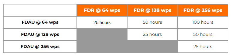
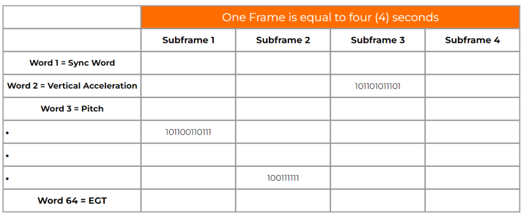
  • Case 2 (inaccurate event detection): – 1 second matters when it comes to exceedance duration and event detection, especially when various recorded parameters are undersampled. Midway through the course you’ll acquire the knowledge of sampling theory to improve the accuracy of your event detection, which will aid you in upgrading or expanding your recording dataframe.
  • Case 3 (parameter deprivation): An airline’s aircraft does not record the air/ground parameter. As such, several events trigger unnecessarily due to the FDM software’s inability to differentiate between the air and ground mode. You’ll learn how to circumvent parameter deprivation by replacing missing parametric data with pseudo parametric programming.

“What an amazing methodolgy for teaching FDM. I thought it would be a standard “death-by-powerpoint” course. Instead, to my surprise, I ended up flying a 737NG sim in the class and generating actual FDM output data for analysis. This gave me the opportunity to intentionally exceed event limits during the flight, which provided me with a thorough understanding and a new view point regarding how caution, warning, & alert event levels should be programmed. I would highly recommend this course for all FDM/FOQA & Safety departments around the globe!”

Abu Hanifah
FDM/FOQA Analyst & Consultant

Learn more about how FDM 101 can benefit your organization

Learn more about how Flight Data Simulation can benefit your organization.

Learn more about how DAE for Aerospace can benefit your organization

How do I modify my FDR to record more than 25 hours?

You can modify the program pins at the rear of the SSFDR to uptick your recording hours. For example, if you have a Honeywell PN 980-4700-XXX installed, you can alter the ‘ground/open’ discrete wiring at pin 17 & 18 of the SSFDR mating connector to increase your recording capacity.

How can determine the amount of hours recorded by my FDR?

The amount of recorded hours is dependent on a combination of your FDAU wps output and FDR maximum allowable recording speed. If there is a one to one relationship between the two units, i.e. – 64 wps FDAU with a 64 wps FDR, you will record the last 25 hours of flight data. This also applies to the case when the FDAU and FDR are both 128wps, 256wps, or even higher. If there is a mismatch between the FDAU and FDR speed, a small and simple calculation can be made to determine actual flight hour recording capacity. See the figure below for the various possibilities:

How can I determine the speed of my Flight Data Recording system in words per second (wps)?

There are basically 4 ways to determine your speed, with the 4th being a bit more involved. First, the speed should be listed or documented in chapter 31 of your aircraft Maintenance Manual and/or Wiring Diagram Manual. However there are times when for some reason, the required information cannot be found. If this is the case, as a second method, you may reference the CMM or technical specification for your Flight Data Acquisition Unit (FDAU). If you are still unable to find this information, you may contact the aircraft manufacturer for the wps or review your previous FDR download analysis reports. Please keep in mind, the OEM will only know the as-delivered configuration of your aircraft. If there were modifications to your aircraft post-delivery – manufacturer unaware of the changes – youll need to contact us for an analysis of your raw data. Using our software we can determine the wps of your system.

With regard to Flight Data Recorder Systems, what exactly does wps imply? I have noticed this abbreviation in our FDR documentation and in communications with the manufacturer several times:

WPS = words per second. A word (12-bits in length) contains binary data which represents a specific parameter value. Please see figure 1 below. Your FDR records in frames (4 second intervals) and each frame contains 4 sub frames (one sub frame = 1 second). With each second that goes by a specific quantity of words are recorded into memory. If you operate a 64 wps FDR system, you will record 64 12-bit words in one second. The higher the word capacity the more information you can record.

What is a Dataframe Layout (DFL)?

A DFL, also known by the name Logical Frame Layout (LFL), Dataframe Interface Control & Requirements Document, and many other names depending on the manufacturer, is a document which specifies the FDR, QAR, or DAR Parameter Word (location), Recording Speed, Sampling Rate, Bits, and Conversion formulae for your recording system.  

Contact our Team

Contact our Team